Friday, March 18, 2016

Learning By Doing: Challenges

Main Page | CCNA Exercises | CCNP Labs

UP To The Challenge?


Let's begin then!
  1. Calculating Subnets.
  2. Analyze TCP Header During Transmission.
  3. Installing Packet Tracer.
  4. Cisco Router and Switch Initial Configuration with Packet Tracer.
  5. CDP: Building Topology Diagram.
  6. Lab 1-1: Switch Startup and Initial Configuration.
  7. Lab 1-2: Troubleshooting Switch Media Issues.
  8. Lab 2-1: Router startup and Initial Configuration.
  9. Lab 2-2: Internet connections - Static NAT.
  10. Lab 2-2: Dynamic NAT.
  11. Lab 2-2: Port Address Translation (PAT).
  12. Lab 3-1: Improving Device Security.
  13. Lab 3-2: Device Hardening. 
  14. Lab 3-3: Using ACLs to filter IP based traffic. 


Lab 3-3: Using ACLs to filter IP based traffic

Previous Lab | Exercises | Next Lab


Lab pre-requisites:

Lab 2-1 Packet Tracer Topology Download.

Topology Diagram


This is continuation of the previous lab related to basic security.
  
Task 1: Configuring an ACL (Access Control List).


In this exercise assumptions have been made:

PC1 (IP Address: 10.1.1.100/24) is allowed to to access Server (172.16.1.100) using any protocol.

PC2 (IP Address: 10.1.1.101/24) CANNOT use telnet Server. All other traffic is allowed.

There are few ways of constructing ACL. Here's one of them:

Step 1
Configure ACL statements:


Branch#conf t

Enter configuration commands, one per line. End with CNTL/Z.

Branch(config)#access-list 100 deny tcp host 10.1.1.101 host 172.16.1.100 eq telnet

Branch(config)#access-list 100 permit ip any any

Branch(config)#

Step 2
Apply the ACL on Fas0/0 interface blocking incoming packets.

Branch(config)#int f0/0

Branch(config-if)#ip access-group 100 in

Branch(config-if)#

Branch#show access-list 100
Extended IP access list 100
deny tcp host 10.1.1.101 host 172.16.1.100 eq telnet
permit ip any any
Branch#

Notice
Packet Tracer does not provide us with index number next the ACL statements (on real equipment they are present and can be used to remove statements using 'named' acl syntax. 

Notice
Packet Tracer does not have 'show ip int f0/0' command implemented properly. This command normally displays whether incoming and/or outgoing ACL is applied on the interface.
  
Notice
Packet Tracer is somewhat limited here. We cannot enable http server (ip http server) on HQ router in order to properly test the ACL.


Also 'named' ACLs are not working in the version of Packet Tracer I am using. This does not allow me to show you how to re-sequence statements, remove statements, and squeeze statements between other ones.

Verification:

Notice
I have tested ACL using PC2 and telnet is NOT being blocked as expected. This proves that version of Packet Tracer I use is NOT working properly.


Previous Lab | Exercises | Next Lab

Wednesday, March 16, 2016

Lab 3-2 Device Hardening


Lab pre-requisites:

Lab 2-1 Packet Tracer Topology Download.

Topology Diagram


This is continuation of the previous lab related to basic security.
  
Task 1: Managing unused ports on a Switch.
Task 2: Using Switchport port-security.
Task 3: Disable unused services.

Since all the switch ports are 'up' by default, this means that creating any connection to a port (connecting a device to a port), will cause the port to go up. This can create a problem for an administrator, as the users have access to the access switch ports through sockets in a wall or a floor. It is in the best interest of administrator to control who can plug new devices into the network. 

Task 1: Managing unused ports on a Switch.

As an example let's disable the following ports on SW1:
Fas0/2, Fas0/4-12, Fas0/14-24.

In order to do it in 'one shot' we are going to use the range command. It allows us to access the range of ports. If ports are contiguous, the range command uses a hyphen as separator, if not a comma is used as shown below:

SW1(config)#interface range fas0/2,fas0/4-12,fas0/14-24

SW1(config-if-range)#description UNUSED

SW1(config-if-range)#shutdown

I have thrown in the 'description', just to make sure that the ports are disabled for a reason.

Verification in Packet Tracer would be to type in:

SW1#show run

Notice
If you are using a real equipment I suggest that you used the following command:

SW1#show interface status | include disabled

This will display all the ports you have disabled filtering the ones that have not been disabled.

Task 2: Using Switchport port-security.

Now, let's fool around with port security. Suppose we want to ensure that port fas0/13 currently servicing our Branch router (fas0/0), will only allow its mac address as the source mac address. Port security can be applied.

Try to remember the few things realated to port security:
  • In order to enable port security, 'switchport mode access' is required on the port as by default all ports are running 'dynamic' mode (Dynamic Trunking Protocol). Only ports in truly 'access mode' can be enabled for port security by default.
  • If you apply port-security the following security template will be applied: (only 1 mac address can be serviced on the port, the first mac address learned becomes the secure one, this mac address is NOT copied to the port configuration, the violation action is shutdown.
 More information on the options in another post.

Let's configure the following on the port fas0/13 (connection to Branch):
  • Only 1 mac address allowed (Branch fas0/0)
  • Upon violation: shutdown the port (err-disable)
SW1(config)#int f0/13
SW1(config-if)#switchport mode access

SW1(config-if)#switchport port-security

SW1(config-if)#


Verification:

       
Based on the test we can say the following:

Port fas0/13 is currently in secure mode (Secure Port).

Only 1 mac address is allowed (MaxSecureAddr Count).

The first learned mac address has become secure (CurrentAddr Count).

There was no violation reported (SecurityViolation Count).

If there is transmission hitting the port fas0/13 with the illegitimate mac address, the port is going to be 'shutdown' (put in error-disable state).

Another way of checking this:


Notice
If the port is err-disabled, there are only two ways to bring it up:
  1. Disable the port (shutdown), and re-enable manually (no shutdown).
  2. Use errordisable recovery (not taught in CCNA courses).
Display the current secure mac address:


Notice
Packet Tracer does not have this feature fully implemented (it does not behave like it would on a real switch).

In case you have a real equipment, you can do the following:

Configure Branch fas0/0 with a new mac:

Branch(config)#int f0/0

Branch(config-if)#mac-address 0008.eeee.eeee

Branch(config-if)#


In a few seconds, the router Branch will send 'gratuitous arp' message. Its source mac-address changed and will cause the violation.


The port of the SW1 (fas0/13) will go 'down' and be placed in error-disabled mode. 


You could then check this by issuing one of the two commands:


SW1#show interface status | i err

or

SW1#show int fas0/13

Also, SW1 shows the message that causes the violation etc.

Task 3: Disable unused services.

The last task relates to disabling certain services that might create security problem for us.

If you want to disable CDP protocol, you can do this on all interfaces of a switch/router at the same time:

SW1#conf t
SW1(config)#no cdp run

or on per interface basis:

SW1#conf t
SW1(config)#interface fas0/1
SW1(config-if)#no cdp enable

Verification:

SW1#show cdp interface

You will see that Fas0/1 is no listed anymore.

Notice
The below commands are NOT supported in Packet Tracer
On some routers (especially older ones), check the following command for open ports:
show control-plane host open-ports

You might see that HTTP port is open (port 80). Then best practice is to disable it:

Branch#conf t
Branch(config)#no ip http server

Also, a good practice would be to disable the following services (enabled by default on older routers):

Branch(config)#no service tcp-small-servers
Branch(config)#no service udp-small-servers
Branch(config)#no service finger
Branch(config)#no ip bootp server

If you want to learn more on those all sevices check Cisco documentation.


Tuesday, March 15, 2016

Lab 3-1 Improving Device Security


Lab pre-requisites:

Lab 2-1 Packet Tracer Topology Download.

Topology Diagram


In this lab there are four tasks that allow apply a basic security on IOS based switches and routers.
 
Task 1: Device password protection.
Task 2: Remote access using Telnet and SSH.
Task 3: Limiting remote access based on source IP Addresses.
Task 4: Creating a login banner page.

Let's rock and roll!

Task 1: Device password protection.

As an example let's protect access to SW1 starting at protecting the console which by default allows access without any password.

Notice
Switches and routers allow access to the console without prompting for the password. There is 'no login' keyword applied on the by default which means that a user is not prompted for the password even if one is configured. In order to protect the console, you must apply both password and 'login' keyword in order to prompt the user for the password.

SW1 Console Password (use cisco as password):


SW1>enable

SW1#conf t

Enter configuration commands, one per line. End with CNTL/Z.

SW1(config)#line con 0

SW1(config-line)#password cisco

SW1(config-line)#login

SW1(config-line)#

In order to verify this configuration exit session by first typing end and then exit. You will be prompted for the password while creating new console session.

As of now, we only protected console access. We must also protect the privileged exec mode (enabled mode). Let's use password sanfran for a change. The command should be applied in the global configuration mode (if you are still in the console prompt, type in exit to go back to global config mode).

SW1(config)#enable password sanfran

SW1(config)#

Now, if you try to login to enabled mode the system will ask you for password sanfran to grant you access.

The problem is that all the passwords are now showing in clear text format. Check this out:


In order to protect all the existing passwords and the ones you will add in the future, we can encrypt them using Type-7 algorithm known as 'over-shoulder' encryption.

Let's turn on the service now, using global configuraition command as shown below:


SW1(config)#service password-encryption

SW1(config)#

All the passwords are not showing as clear text any more. However, you must still be careful not to disclose those encrypted strings as they can be easily broken on the net. As an example, copy the string below that my system used for sanfran:

08324D400F0B0419

Open the web page below and paste the string into Type-7 box and click 'Crack Password'. See for yourself.


However, this protection is making difficult for a person to guess our password while looking at our screen when we display running-config.

It is much smarter to protect our enabled mode, using a properly encrypted password (either MD5 or SHA-256 will be used dependent of the platform). Let's also use password cisco to do it.

SW1(config)#enable secret cisco

SW1(config)#

Now, let's see what encryption Packet Tracer applied:

Since we have both: enable password (sanfran) and enable secret applied, the question is which password is the system going to use upon our attempt to enter 'enabled mode'? The answer is, the password that is more secure (secret). The only problem is that using secret method we can only protect enabled mode but not console or vty lines (used for remote access). We will handle this as our last thing in this lab.

Lastly, in this task let's allow remote access using Telnet. Here's the basic configuration (password cisco again, although on the production equipment each mode such as console, vty, enabled, should have different passwords).

Let's see if we try to access switch (vty lines) using telnet, what happens when login keyword is applied but there is no password used as shown below:
!

line vty 0 4

 login

line vty 5 15

 login

!

Notice
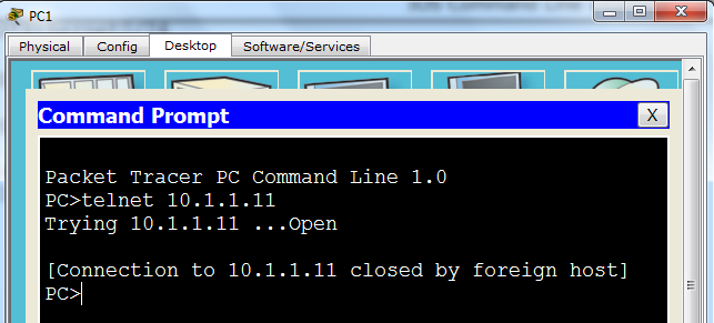
At the moment, my PC1 has IP Address: 10.1.1.100/24.
SW1 has VLAN1 interface configured with IP Address: 10.1.1.11/24

My Telnet session from PC1 results in the following:


Notice
On a real equipment we receive the message:

password required but none set

Task 2: Remote access using Telnet and SSH. 

If we want basic connectivity, assigning password to the first set of vty lines (0-4) can allow up to 5 simultaneous Telnet connections (if more is required apply password on vty lines 5 15 etc.)

SW1(config)#line vty 0 4

SW1(config-line)#password cisco

SW1(config-line)#

Now, Telnet works!


Notice
When you choose password for the production equipment, make sure that they are long (at least 8 characters) and not dictionary keywords. Use upper and lower case with special characters (such as %, ^, & etc.).

However, from security perspective, Telnet connections are not recommended as everything we type (that includes the password) are sent in clear text format. If intercepted, we're in trouble. 

SSH connections are highly recommended. Let's allow SSH support for our remote connections to SW1. These are necessary steps:

Notice
In real network it is recommended to have a centralized login access solution (using AAA server). Here, only local protection is used.

Step 1
Create username and password on the local device (user: ccna, password: cisco)


SW1(config)#username ccna secret cisco

SW1(config)#

Notice
If you want the user account (here ccna) to have access to privileged mode automatically upon connection to vty lines (skipping 'user exec mode'), you can use this instead:

SW1(config)#username ccna privilege 15 secret cisco
SW1(config)#

Step 2
Configure domain name (here cisco.com)
Without domain name RSA public/private keys cannot be generated (command is rejected)

SW1(config)#ip domain name cisco.com

SW1(config)#

 
Step 3
Generate Public/Private key pair used for encryption/decryption of our transmissions while remotely accessed using SSH. Apply key 1024 bit when asked for modulus.

SW1(config)#crypto key generate rsa

The name for the keys will be: SW1.cisco.com

Choose the size of the key modulus in the range of 360 to 2048 for your

General Purpose Keys. Choosing a key modulus greater than 512 may take

a few minutes.


How many bits in the modulus [512]: 1024

% Generating 1024 bit RSA keys, keys will be non-exportable...[OK]


SW1(config)#

Step 4
Change SSH session version to allow only SSHv2 connection (default 1.99 allows both SSHv1 and SSv2).

Default:


SW1(config)#ip ssh version 2

SW1(config)#

After the change:


Step 5

Allow SSH acces.

SW1(config)#line vty 0 4

SW1(config-line)#transport input ssh

SW1(config-line)#login local

SW1(config-line)#

Notice
The command: transport input ssh, only allows ssh. You can add telnet as well but in my opinion that defeats the purpose of this lab.

Also, the command: login local, allows system to use locally defined user (ccna) to log on.

You can verify this configuration by ssh-ing to itself (notice: -l for login not number 1 below):

SW1#

SW1#ssh -l ccna 10.1.1.11


Exit upon verification


Task 3: Limiting remote access based on source IP Addresses.


As an example let us allow PC1 (IP Address 10.1.1.100) to access SW1 using SSH but no other source IP address.

SW1(config)#access-list 5 permit 10.1.1.100

SW1(config)#line vty 0 4

SW1(config-line)#access-class 5 in

SW1(config-line)#

Notice
The last 'implicit' rule says deny any. That means that no other source IP address can get access to vty lines (ssh/telnet).

On real equipment you could add the following ACL statement

SW1(config)#access-list 5 deny any log

Unfortunately, this 'log' option does not work in Packet Tracer.

Task 4: Creating a login banner page.

Notice
Banner in Packet tracer only supports motd option (banner login does not work)

SW1(config)#banner motd &

Enter TEXT message. End with the character '&'.

*************************************************

* Unauthorized Access Strictly Prohibited! *

* ***********************************************

&


SW1(config)#

Notice
Make sure that you start banner with a delimiting character that is not used in the banner itself (I could not use '*' as a delimiting character). You must end with the same character to mark the ending of the message to be displayed upon connection.


Verification
Since only PC1 can access SW1 remotely I added telnet support (no ssh client on PC1) to see the banner upon connection.

SW1(config)#line vty 0 4

SW1(config-line)#transport input all

SW1(config-line)#


The last "security" touch is to use username and password for console 0 access. Since we have username and password locally defined (ccna/cisco), let's use it:

SW1(config)#line con 0

SW1(config-line)#login local

SW1(config-line)#


Cisco Is Easy - Main

  Cisco Basics (CCNA level)  Lessons: Watch Video Tutorials on Youtube 01 - Connecting to Cisco Console Port with MINICOM 02 - Navigatin...